
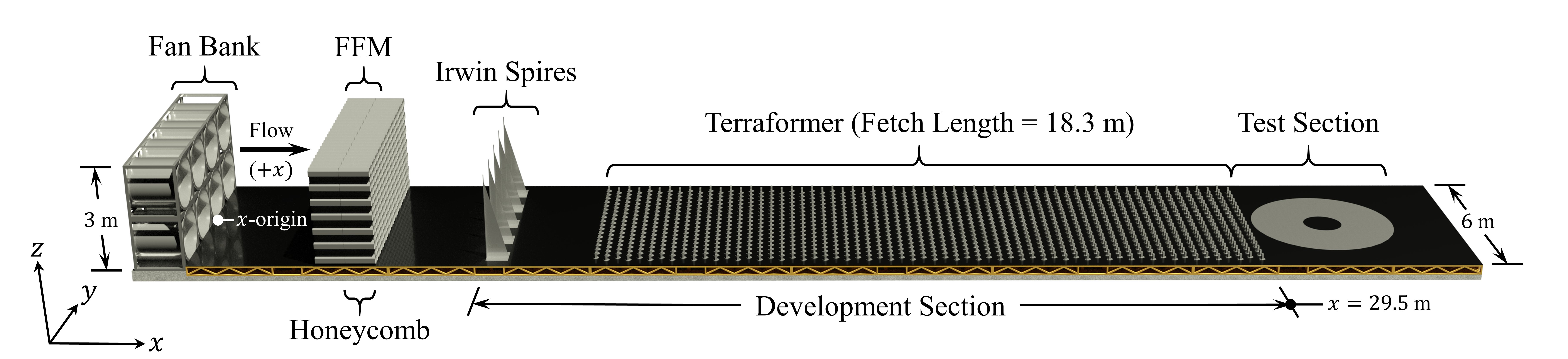
Figure 1. Boundary Layer Wind Tunnel profile
Equipment Resource: The BLWT is a 6 m wide, 3 m tall and 40 m long wind tunnel designed to simulate boundary layer flows to characterize the wind loading and structural behavior, including aeroelastic response of wind-sensitive structures (Figure 1). Unique aspects of this facility are its large size and automated continuously adjustable terrain roughness field (the "Terraformer"). Eight 1.5 m diameter, 75 HP motor driven Aerovent vaneaxial fans can generate speeds of up to 18 m/s while maintaining +/ 1 fan RPM. The Terraformer consists of a 6 m x 18 m field of 1,116 individually controlled 100 mm long x 50 mm wide cuboid elements which raise out of the tunnel floor up to 160 mm each, to form a heterogeneous or homogeneous terrain field. Reconfiguration of the terrain field takes approximately 2 minutes, allowing for rapid testing of multiple terrain configurations. Models are mounted on a 1-meter (current) or 4-meter (future upgrade) diameter turntable for 360° exposure to wind direction.
Experimental Protocol: The BLWT's in-house instrumentation suite includes:
Because of its relatively large size and ability to generate a variety of approach terrains, the UF BLWT offers users tremendous flexibility. Using the standard relationship for similitude in bluff body aerodynamic testing, the parameters for model length scale, velocity scale and time scale can be adjusted to test a very wide range of possible test specimens and wind field conditions. The primary limitation is that the model does not block more than 5% of the tunnel cross section, or 0.9 m2, in order not to deviate from reference tunnel air flow characteristics.
The BLWT may be utilized to study rigid and/or aeroelastic scale models as well as other boundary-layer turbulence research topics (for example, UAVs). Typically, rigid models will utilize the Scanivalve system to quantify pressure distribution around the model envelope using built-in taps. Aeroelastic model response is quantified using a force balance and/or internal instrumentation.
Depending on the specific test protocol, data output may include the following:
All data will be archived to the CI and will be immediately available to the user for interpretation and analysis.
Standard Operating Procedures
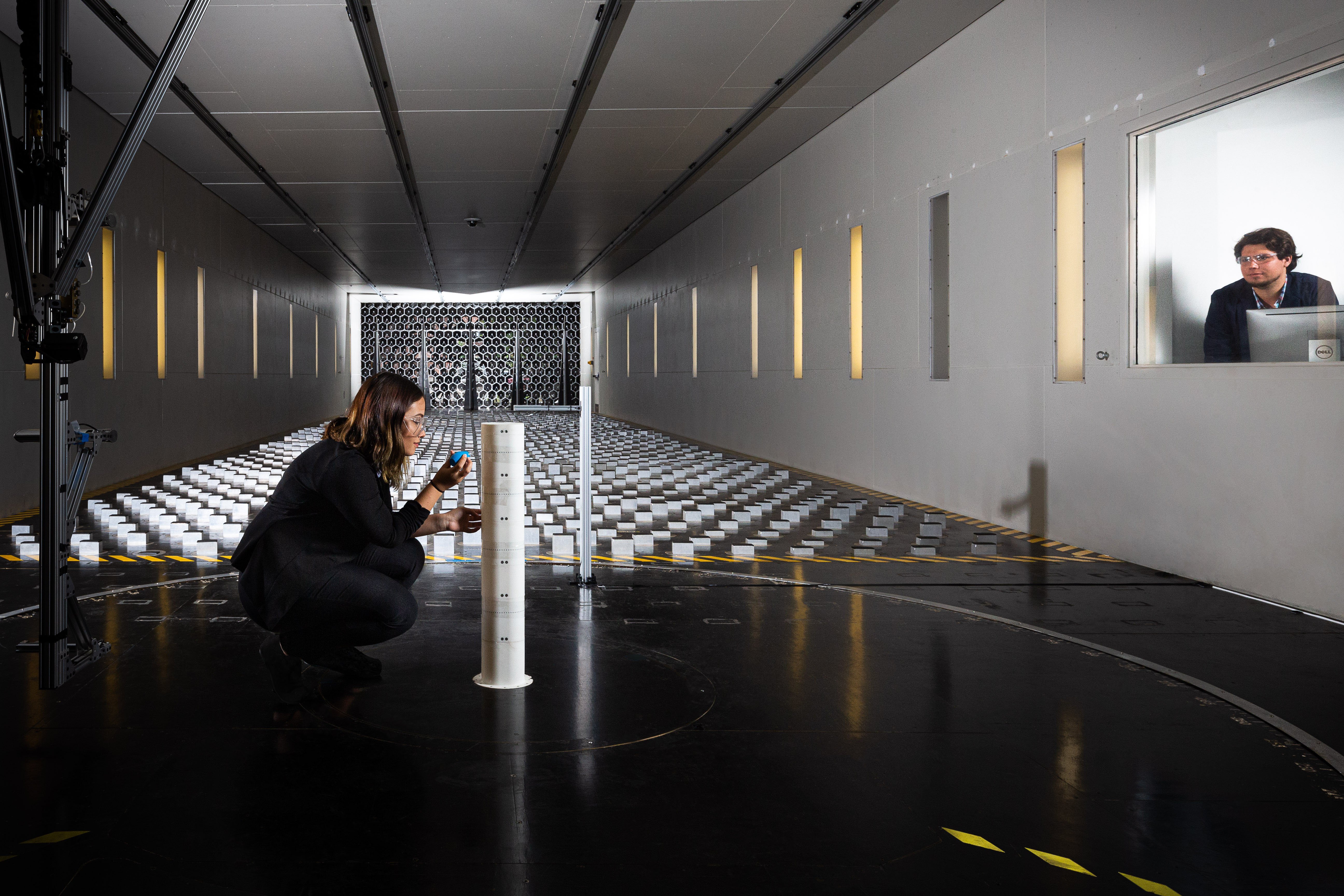
Figure 2: Boundary Layer Wind Tunnel with test specimen and terraformer array
Experimental Resource: The multi-fan Flow Field Modulator (FFM) is a high-resolution flow control device that is integrated into the upwind portion of the BLWT to simulate complex extreme wind phenomena. It is designed to operate in series with the existing vaneaxial fan bank (i.e., primary 448 kW fan system) and consists of a computer-controlled 240kW max 2D array of 319 modular hexagonal aluminum cells containing shrouded three-blade corotating propeller pairs with high-performance 750 Watt brushless DC motors driven by electronic speed controllers (ESC) (Figure 3). Command signals are sent to each cells ESC from custom-built control boards with integrated digital signal processors (DSP). This hardware configuration permits a maximum free discharge velocity of 23 m/s with the primary fan system running at full power, and a peak instantaneous flow acceleration of up to 100 m/s2. Individual cell assemblies incorporate pitot-static tube velocity monitoring and open-loop control. The FFM 319 fan bank is located immediately upwind of the dimensionally identical 319 cell honeycomb (Figure 1). The FFM is mounted on a track system, allowing easy installation in or removal from the BLWT as needed.
Individual instantaneous fan speeds are capable of fluctuating (Figure 4.A) according to stochastic simulations (e.g., reproduced velocity time histories) based on target vertical, across, and along-wind integral length scales to achieve desired nonstationary turbulence properties at the end of a mixing region downwind. Variations in mean fan speeds of cell rows impart vertically stratified steady flowsmean velocity profilesalong the height of the tunnel Figure 4B), accounting for free shear layer interactions, as well as frictional and orifice losses. Additional lateral and vertical turbulence may also be introduced by shifting the phases of adjacent cells, decorrelating the gust structure.
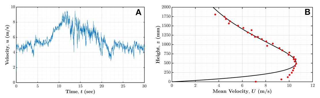
Figure 4. (A) Nonstationary time history measured by a Cobra Probe in the BLWT test section; (B) stationary non-neutral mean velocity profile approximating a scaled gust front (black) measured by a set of Cobra Probes in the BLWT test section (red).
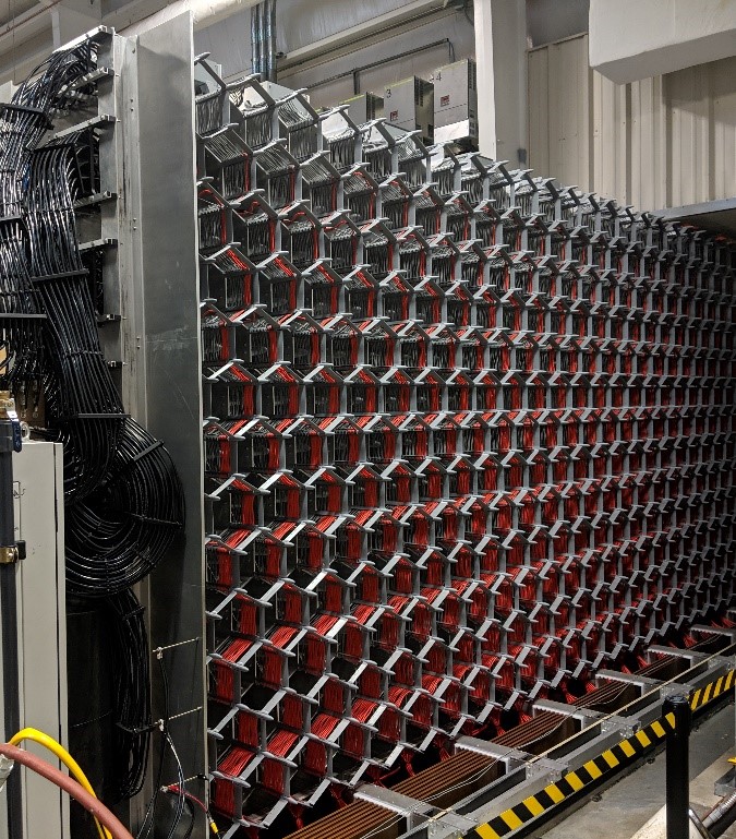
Figure 3. Flow Field Modulator array of 319 modular hexagonal aluminum cells mounted on track system